Pulse-width Modulation
PWM is the acronym for “Pulse Width Modulation”. Pulse width modulation is a very powerful function that is commonly used to control the positioning of servo valves. It is also used for laser pulse control, motion control, light intensity controls and other other applications. The single pulse feature of the function is applicable to any single pulse output need.
A pulse width modulated output signal is one that has a period and an output “on time”, or duty cycle, within that period. For example, a typical servo valve control might have a 20 millisecond period. Valve position is controlled by the “on time” of the output pulse, within this period. The valve may be controlled to a fully closed state with a 1 millisecond pulse on time and fully open with a 3 millisecond pulse (actual times are defined by the valve manufacturer). Partial (5%, 10%, 53%, etc.) opening is generally controlled by an “on time” pulse purportionate between to full open and full closed limits. Standard PWM signals repeat every period increment.
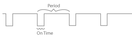
The figure, on the right, illustrates a PWM output signal. Most Velocio PLC digital outputs are “sinking” transistor outputs – so when the output is on, the output sinks, pulling the signal low.
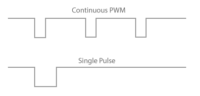
The next figure show a standard PWM on the top, and a single pulse PWM output on the bottom. A single pulse PWM output is active for its defined “on time” within the PWM period. It does not repeat. If you want to output another pulse, your program must execute another “Start PWM pulse” block.
PWMs Application Limits : PWMs can be applied to any digital output that is physically present on the PLC module that contains the application program. That means that any Ace or Branch digital output can programmed to output a PWM signal by the application main program. Any Branch Explansion PLC which has its own program (embedded subroutine) can output a PWM signal from the embedded subroutine. Branch Expansion units that are used a expansion IO, cannot output PWM signals.
Any combination of digital outputs, contained on the PLC with the program, can have PWM output signals. Each active output has its own “on time”. However, the Period is common to all PWM signals on the PLC unit.
PWM in vBuilder
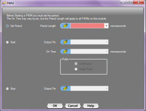
When you place a PWM block in your program, a dialog box, like that shown below, will pop up. With this dialog box, you can Set the PWM Period, Start (continue/adjust) PWM operation, or Stop the PWM.
 PWM Set Period

The Period is common to all PWMs in the PLC. The period is set by selecting the “Set Period” radio button, then either selecting a ui16 tagnamed variable, or entering a number between 100 and 65535. Timing is in microseconds (1 million microseconds = 1 second). That means that the PWM period can range from 100 microseconds to a little over 65 milliseconds.
If the period is set to a value less than 1 millisecond (a setting of less than 1000), only one PWM output will be active. The active PWM output will be the one with the shortest On Time.
If the period is set to 1 millisecond or above, all of the outputs defined for PWM will have active signals.
In summary, to set the period, select Set Period, select or enter a ui16 (unsigned 16 bit integer) number, and click OK.
 PWM Start

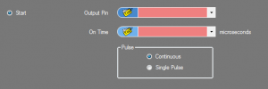
The Start selection defines the Output and the On Time for the PWM signal. It also provides a selection for either Continuous or Single Pulse. If the PWM is to be used for a varying On Time PWM signal, each time the block is executed, the On Time will update its value on the next Period.
In the Output Pin selection, you must enter a tagname for a digital output present on the PLC. The dialog box will allow you to select any bit tagname. However, if the selected tagname is not that of a PLC digital output, the PWM will not execute. If you are starting a PWM in a subroutine, the tagname must be a reference to a PLC digital output.
The On Time can be any ui16 value (0-65535) or tagnamed variable.
If you select Continuous operation, PWM pulses will continue, one pulse per period, until you execute a Stop PWM block for the output. If you select Single Pulse, it will output one pulse on the next Period. After the period is complete, the output will be set according to the program digital output state for that output.
 PWM Stop
To place a block to Stop a PWM ouput, you simply select the Stop radio button and select the tagname of the output. If you are placing the Stop block in a subroutine, place the reference to the output as the Output Pin