Modbus Example
In addition to this example, I’d suggest reading this excellent document on MODBUS that will explain the protocol in detail.
Ace and Branch PLCs are built to communicate Modbus messages. Using Modbus, you can plug your PLC into any PC (or any device with a USB port capable of Modbus communication) and communicate with your custom application.
In this example we’ll create a custom application in Visual Studio using C#. Specifics we’ll cover:
- Assign Tags Modbus Addresses using vBuilder
- Check if PLC is already being used by another Velocio application.
- Connect application to PLC
- Write Bit
- Read Bit
- Write UI16
- Read UI16
- Discuss additional commands and how to read/write remaining data types
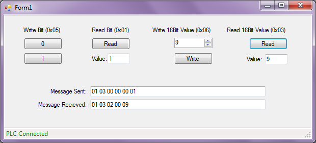
The Application will look like
You’ll Need:
Visual Studio: Here’s a free link to Windows Desktop Version. I think this one requires at least Windows 7. Feel free to download an older version if you need, there isn’t anything in this example that requires the newest version.
vBuilder: Here’s the link to our vBuilder page where you can download it for free.
Example Code:
Click to download the code used in this example
Other Important Documents:
Modbus Application Protocol: This describes the full Modbus Protocol. Velocio PLCs support the 0x01, 0x02, 0x03, 0x04, 0x05, 0x06, 0x0F, 0x10 and 0x17 commands.
Code added after video was made:
We added a subroutine to handle the CRC needed for Modbus Communication. It is called both in the send and the receive routine.
The following code builds on the Example Project above.
Requesting 32Bit Value (I32 or Float)
This is just like the Read16BitMessage in the Example Project, except for the ‘Quantity of 16 Bit words to read’ is set to 2 instead of 1
public void Read32BitMessage()
{
     ArrayList alReturn = new ArrayList();
     alReturn.Add((byte)0x01); // PLC ID# in this example we set it to 1
     alReturn.Add((byte)0x03); // Read 16Bit Command (Modbus Read Holding Registers)
     //In this example we're just sending this to address 0 (called Address 1 in vBuilder).
     // **Note: these are offset by -1 from the # you setup in vBuilder.
     alReturn.Add((byte)0x00); // Starting Address Hi
     alReturn.Add((byte)0x00); // Starting Address Lo.

     //you can set the quantity to read more than 1 contiguous bits
     alReturn.Add((byte)0x00); // Quantity of 16 Bit words to read
     alReturn.Add((byte)0x02); // Quantity of 16 Bit words to read

     sendMessage(alReturn);
}
How to Decode a Float
You may have noticed with the UI16 that the we used the Lower byte as the most significant byte. We’ll need to do that with Float (and all non-bit data types). Just in this case we’ve got 2 16bit words. So we’ll flip the order of bytes in each word. It’ll look like the following. This could be plugged into the si_DataReceivedEventArgs function in the example code.
case 0x03: // Read 16Bit Command (Modbus Read Holding Registers)
case 0x04: // (Modbus Read Input Registers)
     byte[] myFloatArray = new byte[4];
     myFloatArray[0] = readVal[4];
     myFloatArray[1] = readVal[3];
     myFloatArray[2] = readVal[6];
     myFloatArray[3] = readVal[5];
     float myFloat = System.BitConverter.ToSingle(myFloatArray, 0);
     break;
I32 Decode Example
case 0x03: // Read 16Bit Command (Modbus Read Holding Registers)
case 0x04: // (Modbus Read Input Registers)
     byte[] myI32Array = new byte[4];
     myI32Array[0] = readVal[4];
     myI32Array[1] = readVal[3];
     myI32Array[2] = readVal[6];
     myI32Array[3] = readVal[5];
     Int32 myI32 = System.BitConverter.ToInt32(myI32Array, 0);
     break;
I16 Decode Example
This is just a simpler version of the I32 Example
case 0x03: // Read 16Bit Command (Modbus Read Holding Registers)
case 0x04: // (Modbus Read Input Registers)
     byte[] myI16Array = new byte[2];
     myI16Array[0] = readVal[4];
     myI16Array[1] = readVal[3];
     Int16 myI16 = System.BitConverter.ToInt16(myI16Array, 0);
     break;
Creating Float Message to Send to PLC
With a little modification you can use this to send I32values
public void WriteFloatMessage(Single fValue)
{
     ArrayList alReturn = new ArrayList();
     alReturn.Add((byte)0x01); // PLC ID# in this example we set it to 1
     alReturn.Add((byte)0x10); // Write multiple 16Bit values (Modbus Write Multiple Registers)

     //In this example we're just sending this to address 0.
     // **Note: these are offset by -1 from the # you setup in vBuilder.
     alReturn.Add((byte)0x00); // Starting Address Hi
     alReturn.Add((byte)0x00); // Starting Address Lo.

     alReturn.Add((byte)0x00); // Quantity of Registers Hi
     alReturn.Add((byte)0x02); // Quantity of Registers Lo.

     alReturn.Add((byte)0x04); // ByteCount in this case we're sending 4 bytes

      Byte[] myFloatBytes = new Byte[4];
      myFloatBytes = BitConverter.GetBytes(fValue);

      alReturn.Add(myFloatBytes[1]); // Quantity of Outputs Hi of Least Significant Word
      alReturn.Add(myFloatBytes[0]); // Quantity of Outputs Lo of Least Significant Word
      alReturn.Add(myFloatBytes[3]); // Quantity of Outputs Hi of Most Significant Word
      alReturn.Add(myFloatBytes[2]); // Quantity of Outputs Lo of Most Significant Word

      sendMessage(alReturn);
}
As mentioned above Velocio PLCs support several additional messages not described in this tutorial. Check out the Modbus Protocol ( linked above) and using these examples, it should be easy to implement those features.