Stepper Motor Control
Stepper Motors are continuous rotation motors. These motors have a defined number of steps per rotation. You control position and speed by telling the motor when to step and in which direction .
The number of wires differ, but control done by sending step and direction signals.
If you use stepper motors within their limits, they can be very accurate. They do not, however have any feedback to tell you they are at the location you specified. If your application needs this feedback you can add it with an encoder.
Using Velocio’s Motion Output functions, you can control up to 3 Stepper Motors per PLC.
PLC Stepper Motor Example:
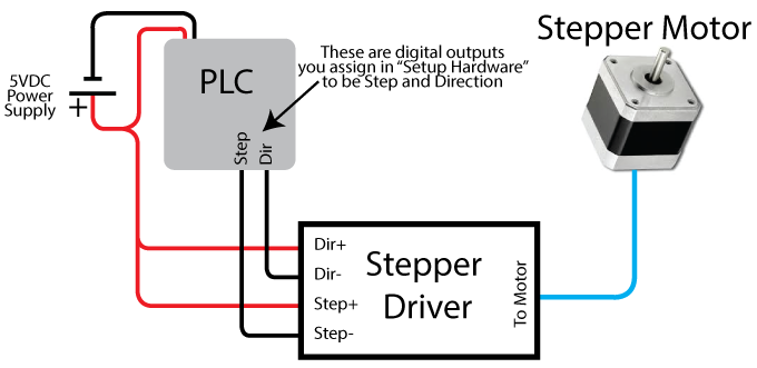
Wiring PLC to Stepper Motor
Your PLC will provide the step and direction pulses, and take care of any needed ramping up/down of speed. You will need a Stepper Driver to interface between the PLC’s step and direction signals and the Stepper Motor. Often the inputs to Stepper Drivers include differential pairs for Step and Direction, consisting of Step+, Step-, Dir+ and Dir-. All Velocio digital outputs are sinking transistor type, so they can make the – connections (Step- and Dir-) in this arrangement and you’ll connect the positive connections (Step+ and Dir+) to the + voltage you’re using to power your PLC. Below is an example showing this wiring.

The Stepper Driver may include other options like Enable. These are often optional and can be controlled using an additional digital output.
PLC Programming for Stepper Motors
Start out by pressing the “Setup Hardware button” (shown right).
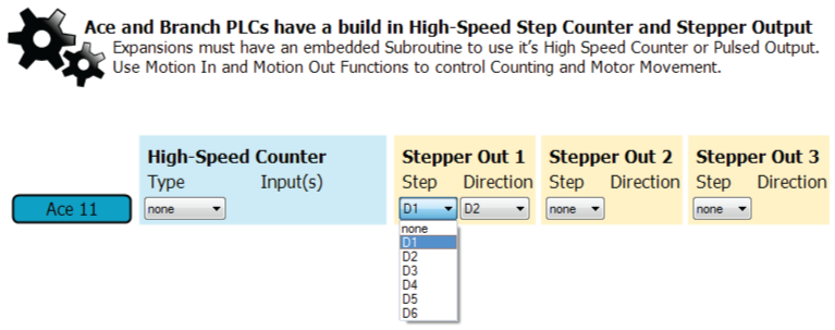
After selecting your hardware, you’ll make it to the Motion Setup page (shown below). You will assign digital outputs to up to 3 stepper motors. Each Motor requires a Step and Direction Pin.
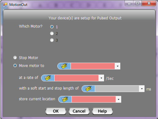
 Once you’ve configured your project for at least 1 Stepper Output, you’ll be able to use the Motion Out function. In it you assign which motor to use, then tell it to Stop or Move. You’ll tell it:
- where to move to,
- what rate to move at and
- what Tag to store the current location at
- Optionally, you can also assign a soft start/stop length, telling it how long to take to reach the speed you specified in “rate” field or to stop.
To control you’re motion, you’ll need 1 more tool: a compare decision block (shown below)

You’ll compare your “store current location” Tag to your “Move motor to” value (or Tag). When they are equal, you’ll know that your motion is complete.
Stepper Motor Programming Example
Here are the files used in this example:stepper_example.zip To use, save file. Unzip files keeping them in a folder together. Open the .vio file inside of vBuilder.
This example is setup like a state machine. If this is a new concept to you, please check out our State machine and other tutorials on our Tutorial Page.
In this example, we tell the Stepper Motor to move a motor. The program waits for a digital input to turn ON, then starts a sequence of movements. The Motor will move:
- to location 200
- to location 0
- to location 400
- to location 0
- to location 600


